Partner Login
Enter your username and password here on order to log in on the partner portal:
No registered partner yet?
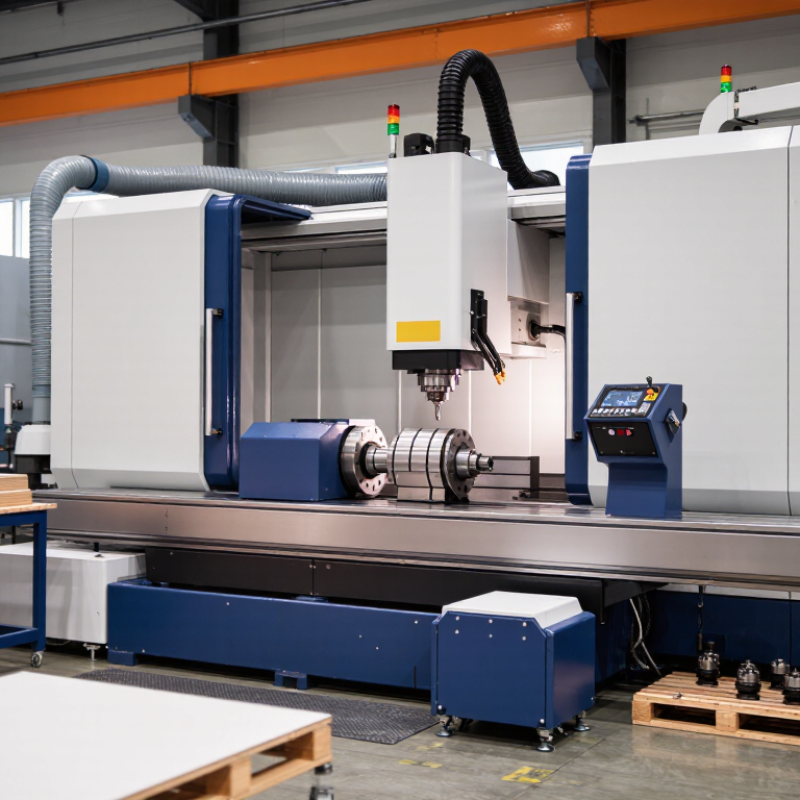
Register nowChoosing a CNC Multifunctional Side Hole Drill requires more than comparing spindle speed, price, or catalogue photos. The machine must match your panel materials, hole positions, production volume, and workshop limitations. A beautiful specification sheet can still disappoint on the factory floor.
Industry data shows why this decision deserves care. The International Federation of Robotics reported 541,302 industrial robots installed worldwide in 2023, reflecting stronger demand for automated production. Meanwhile, Grand View Research identifies CNC machine adoption as a major part of manufacturing modernization, driven by accuracy, repeatability, and reduced manual handling. These reports describe broad market direction, not a guaranteed return for every buyer. Forecasts can sound impressive. Your actual workload matters more.
A practical evaluation should examine drilling accuracy, spindle configuration, tool-changing speed, dust collection, software compatibility, and operator training. Check whether the machine maintains hole alignment after continuous operation. Ask for test samples using your own boards, including laminated panels and thicker materials. Inspect the control interface, emergency systems, maintenance access, and spare-parts support. Small details matter.
Do not overlook total operating cost. Energy use, tooling wear, downtime, calibration, and rejected panels can quickly exceed the purchase price difference. A 2024 Deloitte smart manufacturing survey also emphasizes the importance of connected systems, workforce capability, and reliable production data. That lesson applies here. Automation without dependable data may create faster mistakes.
The best choice is not always the most powerful model. It is the machine that performs consistently, fits your process, and remains supportable for years. This guide explains how to compare each factor with evidence, caution, and real workshop conditions.
Start with the hole diameter, depth, and material. A 6 mm hole through hardened steel behaves differently from a 20 mm hole in aluminum. Record the finished diameter, not only the drill size. The tool may need boring, reaming, or interpolation afterward.
Depth needs a clear reference point. Measure from the actual side face, including any fixture offset. A deep hole can require extra flute length, coolant delivery, and chip evacuation space. Blind holes also need a defined bottom shape. Flat, conical, and relieved bottoms affect tool selection and inspection.
Tolerance must be practical and measurable. For a tight bore, specify the allowable variation in millimeters and identify the inspection method. A probe, gauge, or coordinate measuring machine may produce different results. Check thermal growth during long cycles. It matters.
Axis access often decides the machine configuration. A three-axis setup may reach a simple side hole after rotating the part. Complex angles may require four- or five-axis positioning. Confirm the spindle can approach without colliding with clamps or nearby walls. Leave room for tool changes.
A small trial cut can expose problems early, especially with thin walls or interrupted surfaces. I have seen clean drawings fail because the fixture blocked coolant access. That detail is easy to miss. Recheck the real workholding arrangement before approving the drill.
Choosing a CNC multifunctional side-hole drill begins with spindle matching. The speed range is not a quality score. It must fit the cutting load.
The U.S. Department of Energy reports that motor-driven systems consume about 70% of manufacturing electricity. The IEA also estimates electric motor systems use roughly half of global electricity. Efficiency matters, but torque matters more during deep side drilling. Use the relation P = T × n ÷ 9,550. A 10 kW spindle delivers about 15.9 Nm at 6,000 RPM, but only 4 Nm at 24,000 RPM. Fast is not always strong.
Start with the material, hole diameter, and tool projection. Aluminum may benefit from 18,000–24,000 RPM and balanced tools. Steel often needs lower speed and steadier torque, sometimes near 6,000–12,000 RPM. Check the torque curve, not only rated power. A spindle can sound impressive on paper.
Tooling interface deserves equal attention. BT holders provide familiar rigidity and broad availability. HSK offers shorter gauge length and stronger repeatability at high speed, when clamping and balancing are correct. ISO 12164 defines HSK dimensions, while JIS B 6339 covers common BT interfaces. Confirm the exact taper, pull-stud specification, maximum tool weight, and balance grade. My first selection mistake was trusting RPM alone. The cutter survived, but the hole wandered. That was expensive feedback.
Match spindle capability by checking speed range, available torque, and the BT or HSK tool interface. The chart shows the torque required to deliver a constant 5 kW at common spindle speeds, calculated with P = T × n / 9550.
Tooling note: BT and HSK are different tool-interface systems. Confirm the holder size, balance grade, maximum rated speed, clamping method, and manufacturer specifications before operating at high RPM. Higher spindle speed does not automatically provide higher drilling torque.
ISO 230-2 testing gives buyers a practical way to verify CNC machine accuracy. It examines positioning accuracy and repeatability across each controlled axis. For side-hole drilling, this matters when the spindle returns to several programmed depths. Small positioning errors can shift hole centers, especially on tall cabinet panels or narrow workpieces. Request test results for the actual machine configuration, not a general factory specification.
A reliable inspection should use a calibrated laser interferometer or another traceable measurement system. The technician should test multiple target positions through the useful travel range. Each axis needs repeated movements from different directions. This reveals systematic positioning error, backlash effects, and inconsistent return performance. Temperature should be recorded, because heat from motors, bearings, and the workshop can change results. Let the machine warm up first. Otherwise, the report may look better than daily production.
Pay attention to A, R, and B values in the ISO 230-2 report. Positioning accuracy shows how closely the machine reaches commanded coordinates. Repeatability shows whether it returns to nearly the same location. Bidirectional results are especially useful for drilling operations involving approach changes. Ask when the test was performed and how often it is repeated. A clean report can still hide poor maintenance. That deserves careful questioning. Also inspect sample holes after cutting, because measurement data and real panels do not always agree.
Choosing a CNC multifunctional side-hole drill starts with measurable throughput, not advertised speed. Cycle time should include loading, positioning, drilling, tool withdrawal, and chip clearing. A machine that drills quickly but pauses often may produce fewer parts per shift. Record at least 50 cycles under normal material conditions. Then compare the average time and the longest delay.
Tool life changes the calculation. A cutter lasting 900 holes may outperform a faster cutter lasting 250 holes. Track hole count, edge wear, surface finish, and replacement minutes. Inspect the first and last holes from each tool. In practice, operators often notice quality loss before software records an alarm. That observation matters. However, estimating tool life from one material batch can be misleading. Material hardness and coolant flow may vary.
A true 24/7 duty-cycle rating should cover the spindle, feed system, lubrication, controls, and chip management. Ask for documented thermal tests, maintenance intervals, alarm history, and permitted continuous loads. Check whether the rating assumes short cycles or uninterrupted production. Test the drill for several shifts, including warm starts and tool changes. Measure motor temperature and cycle drift. Small delays become expensive overnight. I would also question ratings without clear testing conditions. That uncertainty deserves a lower production forecast.
How to Choose a CNC Multifunctional Side Hole Drill?
Control quality affects every side-hole operation. Choose a control system with clear screens, stable feedback, and quick parameter access. Operators should adjust spindle speed, feed rate, and drilling depth without navigating confusing menus. Useful alarms should identify overloads, tool wear, and position errors. Simple controls help reduce mistakes during production changes. Do not guess. Test the interface with gloves and realistic lighting before purchase.
Chip evacuation deserves close attention. Side drilling can trap chips inside horizontal passages, causing heat, scratches, or broken tools. Look for directed coolant, accessible chip channels, and strong air assistance where appropriate. Chip flow matters. During a trial, inspect the hole entrance and the machine bed after repeated cycles. A clean surface is better evidence than a brochure claim. I once saw acceptable holes become rough after several warm-up cycles, so thermal stability should be checked.
For European-market equipment, request the CE marking details, declaration of conformity, safety instructions, and relevant technical documentation. CE compliance should match the machine’s actual configuration, not only its catalog description. Verify guarding, emergency stops, electrical protection, and noise considerations. For precision work, specify spindle runout at 0.01 mm or less, then measure it with a calibrated indicator near the tool holder. Check it cold and warm. Tool length, clamping force, vibration, and operator technique can change the result. A tighter number is not always a better process.
| Selection Dimension | Practical Requirement | Recommended Evaluation Data | Why It Matters for Side-Hole Drilling | Verification Method | Priority |
|---|---|---|---|---|---|
| CNC control architecture | Use a controller that supports coordinated multi-axis interpolation, tool offsets, work offsets, probing, and alarm diagnostics. | Confirm the number of controlled axes, simultaneous interpolation capability, program memory, USB/Ethernet transfer, and backup functions. | Side holes often require synchronized positioning, rotary indexing, or interpolation around a workpiece. Limited control functions can increase setup time and positioning errors. | Controller specification Run a sample multi-axis program. | High |
| Control interface and usability | Prefer a clear HMI with tool-life monitoring, offset management, simulation, graphical alarms, and recovery procedures. | Assess display size, language options, access levels, program search, dry-run mode, single-block operation, and operator guidance. | Good interface design reduces incorrect offsets, restart mistakes, and operator training time, especially when drilling different hole orientations. | Live demonstration Review operator manual. | Medium |
| Spindle speed and torque range | Select a spindle range suited to the workpiece material, drill diameter, and tooling system. | Check maximum speed, rated power, continuous torque, speed control resolution, and the usable low-speed torque range. | Small carbide drills need higher cutting speeds, while larger drills and difficult materials need sufficient torque. A high maximum rpm alone does not guarantee suitable cutting performance. | Load test Compare speed-torque curve with tooling data. | High |
| Toolholding system | Use a rigid, balanced holder compatible with the drill diameter and required runout target. | Record holder type, clamping range, balance grade if specified, allowable speed, and gauge-length limits. | Toolholder accuracy and clamping stability directly affect hole position, tool life, surface finish, and total indicated runout at the tool tip. | Measure with a test arbor Check holder certificates. | High |
| Runout requirement | For a ≤0.01 mm runout target, define the measurement location, gauge force, spindle condition, toolholder, and tool projection. | Specify TIR at the holder taper, gauge line, or cutting-tool tip. A practical acceptance check should state the exact measurement point and tolerance. | Runout increases uneven cutting load and hole oversize. The machine spindle, holder, collet, tool, and setup all contribute to the final result. | Dial indicator or electronic tester Measure at a defined gauge length. | Critical |
| Spindle and axis repeatability | Require documented positioning accuracy and repeatability appropriate to the hole-location tolerance. | Review axis repeatability, backlash compensation, thermal compensation, spindle radial/axial runout, and inspection conditions. | Low tool runout cannot compensate for poor axis repeatability, thermal drift, backlash, or an unstable machine structure. | Laser, ball-bar, or calibrated indicator test | Critical |
| Chip evacuation | Provide through-tool coolant, external coolant, air blast, or a combination suitable for hole depth and material. | Check coolant pressure and flow, filtration, tank capacity, chip conveyor or tray design, and access for cleaning. | Effective chip removal reduces recutting, drill jamming, heat buildup, burr formation, and premature tool failure. | Drilling trial Inspect chips, hole walls, and coolant flow. | High |
| Deep-hole capability | Match the machine and tooling strategy to the hole-depth-to-diameter ratio. | Document maximum recommended depth, peck-cycle functions, retract distance, dwell control, and coolant delivery at the cutting edge. | As depth increases, chip packing and heat removal become more difficult. Peck drilling and reliable chip evacuation may be necessary. | Test the target depth-to-diameter ratio | High |
| Coolant and filtration | Use clean coolant with filtration suitable for the process and tool size. | Check filtration rating, tank volume, pump flow, nozzle positioning, leak control, and coolant concentration monitoring. | Fine chips and contaminated coolant can damage pumps, obstruct nozzles, scratch finished surfaces, and reduce drilling consistency. | Inspect filtration system Measure flow at the tool area. | Medium |
| Workholding and access | Ensure rigid clamping and unobstructed access to every required side-hole position. | Evaluate fixture stiffness, datum repeatability, clamping clearance, part support, rotary-table capacity, and collision margins. | Side drilling can introduce lateral cutting forces and tool deflection. Poor support may cause vibration, position errors, or part movement. | Fixture trial Check clamping deformation. | High |
| Machine rigidity and vibration control | Choose a rigid machine structure with adequate guideways, spindle support, and foundation requirements. | Review machine mass, spindle bearing arrangement, guideway type, maximum tool overhang, and recommended cutting conditions. | Vibration negatively affects hole roundness, surface finish, tool life, and dimensional stability, particularly with long side-hole tools. | Cutting trial Monitor sound, vibration, and surface finish. | High |
| CE compliance for EU use | For equipment placed on the European market, request the applicable EU Declaration of Conformity and technical documentation. | Check machinery safety assessment, electrical safety, EMC compliance, guarding, emergency stops, interlocks, instructions, and the CE marking. | CE marking is a conformity declaration by the manufacturer or responsible economic operator; it is not a substitute for checking the actual safety functions and documentation. | Review signed declaration Inspect the machine and safety circuits. | Critical |
| Guarding and interlocks | Require enclosed moving parts, interlocked access doors, emergency stops, and prevention of unexpected restart. | Inspect door-locking devices, safety switches, emergency-stop response, chip containment, visibility, and access during setup mode. | Side-hole drilling creates rotating-tool, flying-chip, coolant, and entanglement hazards. Safety functions must remain effective in normal and setup operation. | Functional safety test Review risk assessment. | Critical |
| Programming and drilling cycles | Confirm fixed cycles for drilling, peck drilling, tapping, dwell, retract, and safe-plane control. | Check support for canned cycles, coordinate rotation, polar or cylindrical interpolation where required, tool-radius compensation, and probing routines. | Suitable cycles help control chip load, reduce programming errors, and maintain consistent results across multiple side-hole locations. | Program validation Run simulation and dry cycle. | High |
| Measurement and inspection | Define acceptance checks for hole diameter, location, perpendicularity, roundness, depth, and runout. | Identify gauges and instruments such as plug gauges, bore gauges, CMM, dial indicators, and calibrated test bars. | Measurement results are meaningful only when the datum system, temperature, gauge method, and inspection uncertainty are controlled. | Inspection plan Use calibrated equipment. | Critical |
| Thermal stability | Assess warm-up procedures and compensation when tight tolerances are required. | Review spindle warm-up cycle, coolant temperature control, ambient-temperature range, and documented thermal drift behavior. | Spindle and machine temperature changes can alter tool position and hole location, even when static runout is within specification. | Repeat measurements after warm-up | Medium |
| Maintenance and serviceability | Prefer accessible lubrication points, clear maintenance intervals, spare-part availability, and diagnostic support. | Check lubrication monitoring, coolant-cleaning access, filter replacement procedure, alarm history, backup method, and service response capability. | Consistent accuracy depends on clean coolant, correct lubrication, stable tooling, and timely correction of spindle or axis problems. | Review maintenance schedule Inspect service access. | Medium |
| Acceptance testing before purchase | Require a documented factory or site acceptance test using the intended material, tool, fixture, coolant, and hole pattern. | Record runout, hole diameter, hole location, cycle time, chip evacuation performance, alarms, and repeatability over multiple parts. | A realistic test reveals the combined effect of the machine, tooling, workholding, cutting data, and operator procedure better than individual specifications. | Signed acceptance report | Critical |
| Overall purchase decision | Choose the machine only when control capability, safety documentation, chip evacuation, workholding, and measured accuracy meet the process requirement together. | Use a weighted scorecard: safety and compliance first, then measured accuracy, process capability, reliability, serviceability, and total operating cost. | A low purchase price or high spindle speed cannot offset inadequate safety, unstable runout, poor chip control, or insufficient axis capability. | Pass / Conditional / Fail Document all open risks. | Critical |