
X

Partner Login

Enter your username and password here on order to log in on the partner portal:

No registered partner yet?

Register now

How to Choose EMT Electrical Connectors for Any Project?

Choosing the right Emt Electrical Connectors is a practical safety decision, not a catalog exercise. Each connector must match the conduit size, wall thickness, wiring method, environment, and installation technique. A connector that fits on the bench may loosen above a ceiling or fail inside a damp mechanical room. Fit matters. So does verification.

NFPA’s Electrical Fires report estimates that electrical distribution and lighting equipment were involved in approximately 32,000 home structure fires annually in the United States from 2015 to 2019. These fires caused about 470 deaths, 1,100 injuries, and $1.3 billion in property damage. Connectors are not the only cause, but poor bonding, exposed edges, and loose fittings can increase system vulnerability. This guide uses NFPA 70, the National Electrical Code, and UL 514B as practical reference points for evaluating connector construction, grounding, and listed applications.

On a real project, examine more than price. Check whether the connector is listed for EMT, accepts the specified conduit diameter, and provides reliable mechanical protection. Compression fittings may suit vibration-sensitive areas, while set-screw types can work well in dry, accessible locations when installed correctly. Consider corrosion resistance near washdown zones or coastal air. Then inspect the finished connection: the conduit should seat fully, the locknut should be tight, and no sharp edge should threaten insulation. Not always simple. Manufacturer instructions still matter, and this guide cannot replace the authority having jurisdiction. A careful choice reduces rework, but it does not remove every installation risk.
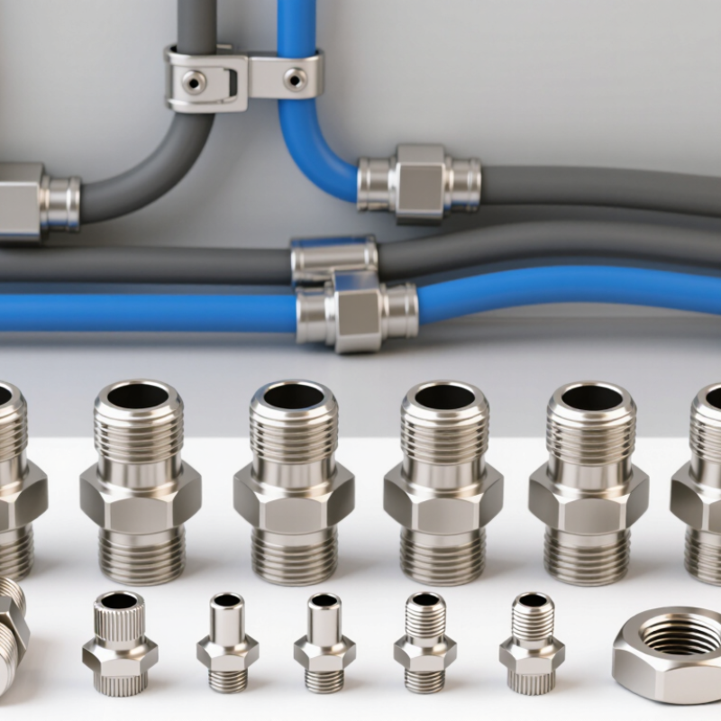
How to Choose EMT Electrical Connectors for Any Project?

Define EMT and Connector Standards: NEC Article 358 and UL 514B

How to Choose EMT Electrical Connectors for Any Project?

Electrical Metallic Tubing, or EMT, is a thin-wall steel or aluminum raceway. NEC Article 358 defines where EMT may be installed and how it must be supported, joined, and protected. It also requires fittings to be listed for the intended use. That requirement matters because a connector may fit the tubing but still lack suitable grounding or environmental protection.

UL 514B provides the product standard for conduit, tubing, and cable fittings. When choosing an EMT connector, check its marking, trade size, material, and connection method. Set-screw connectors suit many dry indoor areas, while compression fittings may provide better resistance to moisture and movement. Wet locations require fittings identified for those conditions. Looks can mislead. A tight set screw does not automatically create a reliable electrical bond.

Inspect the connector and tubing as one system. Remove sharp edges, insert the tubing fully, and tighten the fitting according to its instructions. Confirm that the installation maintains continuity across every joint. Article 358 also affects grounding, support spacing, and protection from physical damage, so connector selection cannot stand alone. On a jobsite, small details matter: a missing locknut, damaged thread, or mismatched metal can create inspection problems. Local requirements may also vary, so the authority having jurisdiction should review uncertain applications. Some choices seem obvious, but field conditions often prove otherwise.

Match Connector Types to Joints: Set-Screw and Compression Designs

Choosing an EMT connector starts with the joint, not the price. Set-screw connectors suit dry, accessible installations where the conduit remains stable. Their screws must bite firmly against clean EMT. A square cut matters. Even a small burr can weaken the connection or obstruct conductors.

Compression connectors use a nut and ferrule to grip the conduit evenly. They are often preferred where vibration, moisture, or maintenance access creates greater risk. However, “compression” does not automatically mean wet-location approval. Check the fitting’s listing and installation instructions. NFPA 70, the 2023 National Electrical Code, requires listed EMT fittings under Section 358.6 and installation according to their listing under Section 110.3(B). That detail is easy to miss.

Field inspections commonly reveal loose set screws, over-tightened nuts, and unclean conduit ends. I still measure twice before choosing either design. NFPA’s Home Structure Fires analysis reported about 32,000 U.S. home fires annually involving electrical distribution and lighting equipment during 2015–2019. The report does not blame EMT connectors directly, but it reinforces the cost of careless workmanship. Select compression fittings for exposed or demanding joints when their listing supports the environment. Use set-screw fittings for controlled, dry runs with reliable access. Then verify continuity, alignment, and torque. No connector fixes a careless cut.

How to Choose EMT Electrical Connectors for Any Project? – Match Connector Types to Joints: Set-Screw and Compression Designs

Connector Design Joint or Connection Typical Application Environmental Suitability Installation Method Grounding Considerations Selection Guidance
Set-screw connector EMT-to-box, enclosure, or other threaded or unthreaded fitting entry Indoor commercial, institutional, and light-industrial installations Generally intended for dry locations unless specifically listed for another environment Insert EMT fully, tighten the set screw to the manufacturer’s specified torque, and verify conduit engagement The connector must maintain electrical continuity between the EMT and the metal enclosure; remove coatings only where required by the fitting instructions Choose when installation speed and simple access are important and the location is dry
Compression connector EMT-to-box, enclosure, or fitting entry using a compression nut and sleeve Commercial, industrial, exposed, and higher-vibration installations Available in designs listed for concrete-tight, rain-tight, or wet-location use; confirm the exact product marking Insert EMT fully, seat the sealing sleeve correctly, and tighten the compression nut as specified Provides a metal-to-metal bonding path when properly installed; use an approved bonding method where required by the installation conditions Choose when moisture resistance, mechanical security, or a more sealed entry is needed
Raintight compression connector EMT-to-weather-exposed box, enclosure, or equipment connection Outdoor equipment, rooftop electrical work, washdown areas, and damp or wet locations Use only when the connector is specifically listed and marked for the required location Ensure the sealing components are correctly positioned and tighten without damaging the seal Confirm that the listed fitting provides the required bonding and grounding continuity for the metal raceway system Prefer this design where rain, spray, condensation, or washdown could reach the connection
Set-screw coupling EMT-to-EMT straight joint Extending a conduit run in dry indoor spaces Typically used in dry locations unless the fitting is specifically listed for a different location Insert both conduit ends to the required depth and tighten each set screw evenly Maintain clean, continuous metal contact and comply with the applicable electrical code requirements for raceway bonding Use for economical straight runs where moisture sealing is not required
Compression coupling EMT-to-EMT straight joint Exposed runs, industrial areas, and installations requiring a tighter mechanical joint Select a version with the required concrete-tight or wet-location listing Insert both conduit ends fully, position the sleeves, and tighten both compression nuts according to the instructions Verify that the coupling is listed for electrical continuity and that the joint remains secure after tightening Use when a sealed or mechanically robust straight joint is more important than the lowest initial cost
Insulated-throat connector EMT entry into a box or enclosure where conductor protection is a priority Installations with limited working space or conductors that may be vulnerable to abrasion Environmental rating depends on the complete connector design and listing Install the connector securely and confirm that the insulated throat is not cracked, displaced, or obstructed The insulating throat protects conductors but does not replace the required metal bonding path Select when conductor insulation protection at the raceway entry is especially important
Important selection checks: Verify the EMT trade size, connector type, enclosure opening, location rating, conductor capacity, and electrical continuity requirements. Product markings and the applicable local electrical code take precedence over this general comparison. Set-screw and compression fittings must be installed according to their listing and manufacturer instructions.

Select Trade Size: EMT Ranges from ½ to 4 Inches Under NEC 358.20

How to Choose EMT Electrical Connectors for Any Project?

Trade size controls connector compatibility. Under NEC 358.20, EMT is available from ½ inch through 4 inches. These sizes describe nominal conduit categories, not exact outside diameters. For example, ½-inch EMT measures about 0.706 inches outside, while 2-inch EMT measures about 2.197 inches. That difference matters when selecting couplings, connectors, locknuts, and supports. Always match the connector to the conduit’s trade size and listed use.

Space planning comes next. A crowded ½-inch raceway can complicate conductor pulling and future maintenance. Yet oversized EMT may increase bending effort, support demands, and material cost. NEC Chapter 9 tables provide conductor areas and raceway-fill rules, while Table 358.20 identifies EMT dimensions. NFPA research on 2016–2020 U.S. home fires estimated 32,580 annual fires involving electrical distribution and lighting equipment. Good fitting selection cannot prevent every failure, but it can reduce loose connections and mechanical damage.

Inspect the job conditions. Outdoor exposure, vibration, sharp bends, and dissimilar metals may require different connector materials or sealing methods. I have found that installers often measure conduit by diameter instead of trade size. That mistake is easy to make. It can delay installation. Check the product listing, NEC requirements, and local amendments before ordering. Clearance also deserves a second look. A technically correct connector may still be impractical beside a junction box or panel.

Verify Conduit Fill: NEC Chapter 9, Table 1 Limits Fill to 40%

How to Choose EMT Electrical Connectors for Any Project?

Selecting an EMT connector starts with the raceway, conductor count, and installation environment. NEC Chapter 9, Table 1 limits conduit fill to 40% when three or more conductors share the raceway. The limit drops to 31% for two conductors and rises to 53% for one conductor. These figures come from NFPA 70, the National Electrical Code, and should be checked against the adopted local edition.

A rushed calculation can look reasonable. It may still create crowded conductors, difficult pulling, and excessive heat. NFPA’s Electrical Fires report identified approximately 35,150 U.S. home fires involving electrical distribution and lighting equipment annually from 2015–2019. Proper sizing cannot prevent every failure, but it reduces avoidable installation stress. Choose compression or set-screw connectors according to the EMT type, enclosure location, grounding method, and manufacturer-listed application. Verify connector dimensions before counting usable interior space.

Tips: Measure the actual conductor insulation diameter, not only its circuit rating. Use the NEC Chapter 9 conductor areas, then compare the total with the raceway’s permitted area. Leave practical pulling room when possible. I sometimes find that a design passes the 40% rule but feels unnecessarily tight during installation. That is a warning worth respecting. Check fittings, couplings, and bonding continuity before closing the enclosure.

Confirm Grounding and Bonding: NEC 250.118 Recognizes EMT as an EGC

How to Choose EMT Electrical Connectors for Any Project?

EMT connectors do more than secure conduit to a box. They can help maintain the equipment grounding path. NEC 250.118 recognizes EMT as an equipment grounding conductor when the raceway is properly installed. The fittings must be listed for grounding and bonding. The entire path must remain electrically continuous.

Choose connectors that match the EMT trade size, box opening, and installation environment. Compression fittings often suit locations exposed to vibration or moisture. Set-screw fittings can work well in dry, protected areas when installed correctly. Follow the manufacturer’s torque instructions. A loose screw can interrupt bonding, even when the connector looks secure. Small details matter.

Inspect every coupling, connector, locknut, and bushing. Remove paint or debris where metal-to-metal contact is required. Use bonding locknuts or jumpers when the installation demands them. Do not assume that a tight mechanical connection provides a reliable grounding path. Test continuity with suitable equipment after assembly. Document the result when project records require it.

A practical check.

The current NEC edition and local amendments should control the final decision. Experienced electricians still review the path from the equipment enclosure to the source. That review can reveal an overlooked fitting or damaged thread. EMT is a dependable grounding method, but only when its connections remain continuous, secure, and properly bonded.