
Partner Login
Enter your username and password here on order to log in on the partner portal:
No registered partner yet?
Register nowChoosing the right Circuit Breaker Distribution Panel is not simply a matter of counting outgoing circuits. It requires a clear view of load demand, fault levels, installation conditions, and future expansion. The International Energy Agency’s Electricity 2024 report expects global electricity demand to grow strongly through 2026. That growth places greater pressure on reliable low-voltage distribution equipment. A panel selected only for today’s load may become restrictive sooner than expected.
A sound evaluation begins with the electrical schedule. Record continuous loads, motor starting currents, available fault current, and ambient temperature. Then verify breaker ratings, busbar capacity, enclosure protection, and space for additional circuits. IEC 61439 provides a recognized framework for low-voltage switchgear assemblies, while UL 67 addresses panelboard construction in North America. These standards support safer decisions, but they do not replace project-specific engineering. The installation environment matters. Dust, moisture, heat, and limited access can change the correct enclosure and maintenance approach.
Do not ignore coordination.
Protective devices should operate selectively where practical, reducing unnecessary shutdowns. Energy monitoring, surge protection, and arc-fault or ground-fault protection may also deserve consideration, depending on the application and local requirements. A common mistake is choosing the cheapest panel without reviewing lifecycle costs, documentation, or spare capacity. That approach can create crowded wiring, difficult troubleshooting, and expensive upgrades. Still, every project has limits. Oversizing equipment is not automatically better. Careful comparison, qualified review, and honest reflection on future needs lead to a Circuit Breaker Distribution Panel that performs reliably in real conditions.
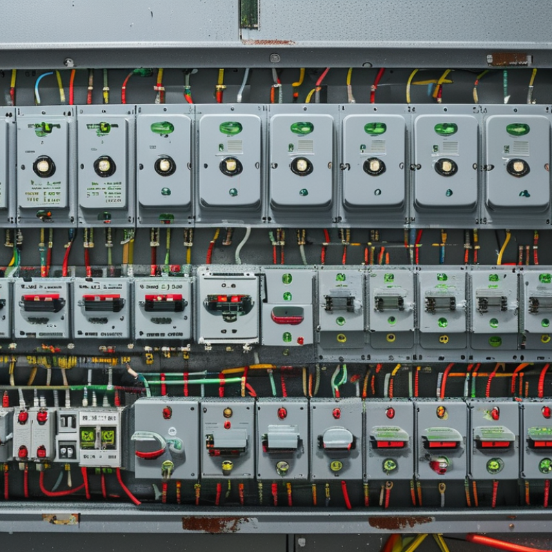
A circuit breaker distribution panel is the control center for a building’s electrical supply. Its type should match the installation, not merely the available wall space. Residential panels often use compact single-phase layouts for lighting, outlets, and household equipment. Commercial panels usually need higher capacity, three-phase distribution, and clearer circuit separation. Industrial applications may require larger enclosures, stronger fault ratings, and space for future feeders.
Main breaker panels disconnect the entire installation from the incoming supply. Main lug-only panels depend on an upstream disconnect and suit some sub-distribution points. Outdoor panels need weather-resistant enclosures, sealed cable entries, and protection from moisture. In dusty or corrosive areas, enclosure selection becomes a safety decision, not a cosmetic choice. A qualified electrician should verify load calculations, conductor sizes, interrupting ratings, and local code requirements before installation.
In practice, I check the panel’s bus capacity and available ways before choosing its dimensions. A panel that fits today may become restrictive after a heat pump or workshop circuit is added. Measure twice. I also label every circuit clearly, because rushed labeling creates dangerous confusion during maintenance. One common mistake is selecting breakers first and forcing the panel to accommodate them. The panel, breakers, wiring method, and enclosure must work as one system. I have seen neat installations fail this basic planning test. Rechecking assumptions is worthwhile, especially when the building’s use may change.
Match the distribution panel to the building’s electrical system, expected load, available space, and future expansion needs. The chart compares common nominal system voltages associated with residential, commercial, and industrial applications.
Residential panels commonly serve 120/240 V single-phase systems, commercial panels often serve 208Y/120 V three-phase systems, and industrial panels frequently distribute 480Y/277 V three-phase power. Actual requirements depend on the utility supply, connected loads, fault-current rating, enclosure environment, and applicable electrical codes.
Choosing a circuit breaker distribution panel starts with the building’s actual electrical load. List every load, including lighting, receptacles, heating, pumps, kitchen equipment, and future charging equipment. Record each nameplate rating in watts or amperes.
The U.S. Energy Information Administration reported average residential electricity consumption of 10,791 kWh in 2022. That figure describes energy use, not panel capacity. Peak demand still matters more. Apply demand factors carefully, then check continuous loads at 125% under applicable electrical codes. A neat calculation can still be wrong when motor starting current is ignored. Measure existing circuits when possible.
Voltage and phase requirements must match the incoming supply and equipment ratings. A 120/240-volt single-phase panel differs from a 208Y/120-volt three-phase system. Confirm voltage at the service, not from memory. Three-phase equipment needs correct phase rotation and balanced loading. Single-phase circuits should be distributed across phases to reduce neutral current. The IEA’s Electricity 2024 report expects global electricity demand to grow by nearly 4% annually through 2026. Future electrification deserves space and capacity.
Tips: Create a load schedule with circuit name, voltage, phase, amperage, and expected duty cycle. Leave spare breaker positions, but do not assume spare space means spare capacity. Ask a qualified electrician to verify fault current, conductor sizing, and service limits. One overlooked appliance can change the design.
How to Choose the Right Circuit Breaker Distribution Panel?
Selecting the right panel begins with an accurate load calculation, not the number of rooms. Add the expected demand from lighting, receptacles, heating, cooking equipment, pumps, and future appliances. A qualified electrician should verify the calculation against local electrical codes. Oversizing may increase cost, while undersizing can create heat, nuisance trips, and limited expansion.
Panel capacity must match the service rating and the conductors feeding it. Check the main breaker rating, busbar capacity, available fault current, and enclosure type. Indoor panels may not suit damp garages, workshops, or outdoor locations. Space also matters. A panel with twelve circuits may appear adequate today, yet electric vehicle charging or a heat pump could require several additional positions. Leave room.
Circuit configuration should separate high-load equipment from general-use circuits. Dedicated breakers are often appropriate for ovens, water heaters, and air-conditioning units. Safety devices may also be required, depending on local rules and the circuit location. Experienced installers label every breaker clearly and balance loads across the phases where applicable. That choice is easy to miss. Measure twice. A practical mistake is planning only for present appliances; households change faster than panels do. Reviewing the panel schedule after installation can reveal unclear labels, unused assumptions, or a circuit that should have been separated.
How to Choose the Right Circuit Breaker Distribution Panel?
Choosing a distribution panel starts with safety, not appearance. Check its protection against overloads, short circuits, and electric shock. A residual-current device may provide extra protection in wet or high-risk areas. Confirm the enclosure rating before installation. Dust and moisture can enter through small gaps. The panel should also include clear labels, secure covers, and adequate heat dissipation. One detail is easy to miss.
Standards matter because they define testing, insulation, spacing, and fault-handling requirements. Select a panel certified for the electrical system and approved under applicable local regulations. Then compare voltage, current rating, phase arrangement, and available fault current. Compatibility is equally important. Breakers must fit the panel busbar and mounting system correctly. Never force a part into place. Installation conditions also affect performance, including wall space, cable entry, ambient temperature, and access for maintenance. In practice, crowded panels often create avoidable heat and wiring problems. I would recheck the layout before ordering, because drawings can hide real site limitations.
Tips: Measure the available wall space first. Photograph cable routes and entry points. Leave room for future circuits. Verify every rating from the technical documentation. If the installation feels uncertain, ask a licensed electrical professional to inspect it. Small assumptions can become expensive faults.
| Selection Dimension | Recommended Data or Typical Range | What to Check Before Selection | Relevant Standard or Technical Basis |
|---|---|---|---|
| System Voltage | Single-phase: 120/240 V or 230 V Three-phase: 208Y/120 V, 400Y/230 V, or 480Y/277 V | Confirm the panel busbar, incoming device, neutral arrangement, and circuit breakers are rated for the actual line-to-line and line-to-neutral voltage. | Electrical system design documents; IEC 61439-1/-2 or applicable national installation rules. |
| Rated Current | Common panel ratings: 63 A, 100 A, 125 A, 225 A, and 400 A | Select a rating equal to or greater than the calculated maximum demand current. Allow practical capacity for future circuits without exceeding conductor or service limits. | Load calculation requirements under the applicable electrical code; panel assembly manufacturer data. |
| Short-Circuit Withstand or Interrupting Rating | Typical branch protection: 6 kA to 10 kA Higher fault levels may require 15 kA, 25 kA, or more | The breaker interrupting rating must be at least the prospective short-circuit current at the installation point. Do not rely only on the normal load current rating. | IEC 60947-2, IEC 60898-1, UL 489, or the applicable local standard. |
| Main Incoming Device | Main circuit breaker, switch-disconnector, or isolator sized for the panel rating | Verify overcurrent protection, isolation capability, pole count, neutral switching requirements, and compatibility with the enclosure and busbar system. | IEC 60947-2; IEC 61439; applicable national wiring regulations. |
| Number of Ways | Common configurations: 8, 12, 18, 24, 36, or 48 outgoing ways | Count existing circuits, dedicated loads, spare spaces, and special modules such as residual-current protection or surge protection. Reserve approximately 10–20% spare capacity where practical. | Project load schedule and future expansion requirements. |
| Residual-Current Protection | Typical sensitivity: 30 mA for additional personal protection; 100–300 mA for selected fire or equipment protection applications | Confirm whether an RCD, RCCB, RCBO, or GFCI is required. Select the correct Type AC, A, F, or B according to the connected loads and possible residual-current waveform. | IEC 61008, IEC 61009, IEC 62423, or applicable local regulations. |
| Surge Protection | Type 2 SPD for many building distribution applications; Type 1+2 where lightning-current protection is required | Check system earthing arrangement, maximum continuous operating voltage, discharge current, backup protection, conductor length, and connection to the main equipotential bonding system. | IEC 61643-11 and IEC 60364-4-44; local lightning and surge-protection rules. |
| Protection Curve and Trip Characteristics | Common miniature circuit-breaker curves: B, C, and D Typical magnetic trip ranges: B = 3–5 × In, C = 5–10 × In, D = 10–20 × In | Select the curve based on inrush current and conductor protection. Curve D should only be used when the installation has sufficient fault current to operate the breaker promptly. | IEC 60898-1; manufacturer-certified time-current characteristics. |
| Pole Configuration | 1P, 1P+N, 2P, 3P, 3P+N, or 4P | Match the number of poles to the circuit arrangement, neutral requirements, phase separation, and isolation rules. Neutral bars must not be bonded incorrectly downstream of an RCD. | Applicable wiring code and system earthing arrangement. |
| Busbar and Breaker Compatibility | Busbar current rating commonly matches or exceeds the panel rating; breaker mounting may be plug-in, bolt-on, or DIN-rail | Use only breakers, busbars, terminals, shields, and accessories approved for the specific panel assembly. Check pitch, mounting method, terminal size, polarity, and torque values. | IEC 61439-1/-2; UL 67; certified assembly documentation. |
| Enclosure Protection | Indoor dry areas: IP30–IP40 or equivalent Dust or splash exposure: IP54 or higher as required | Choose an enclosure suitable for dust, water, impact, corrosion, and accidental contact. The door, cable entries, glands, and unused openings must maintain the required protection level. | IEC 60529 IP ratings; NEMA enclosure classifications where applicable. |
| Installation Environment | Typical reference ambient temperature: 30–40 °C Higher temperatures may require derating or ventilation | Assess ambient temperature, humidity, altitude, vibration, condensation, corrosive gases, UV exposure, and indoor or outdoor placement. Apply the assembly manufacturer’s derating factors. | IEC 61439 environmental service conditions; installation instructions. |
| Thermal Management | Provide ventilation or increased enclosure size when heat-producing devices are densely installed | Check total power loss from breakers, terminals, busbars, and electronic devices. Avoid filling every available way when continuous high-load circuits are present. | Panel assembly temperature-rise verification under IEC 61439 or equivalent requirements. |
| Cable and Terminal Capacity | Terminal range must match the selected conductor cross-section and material | Verify copper or aluminum compatibility, conductor size, stripping length, bending space, lug dimensions, and tightening torque. Do not place more conductors in one terminal than permitted. | Breaker and panel terminal ratings; applicable conductor installation rules. |
| Working Space and Accessibility | Maintain clear access in front of the panel; many codes use approximately 900 mm depth and 750 mm width as minimum working-space references, subject to local rules | Keep the panel accessible, dry, well lit, and free from storage. Provide safe access for operation, testing, maintenance, and emergency isolation. | NEC 110.26 or equivalent national electrical installation requirements. |
| Circuit Identification | Permanent labels for the main supply, each outgoing circuit, neutral, earth, and special protective devices | Labels should be clear, durable, and consistent with the final circuit schedule. Identify sources that can backfeed the panel, such as generators or photovoltaic systems. | NEC 408.4 or equivalent circuit-identification requirements. |
| Earthing and Bonding | Separate protective-earth and neutral arrangements where required by the system design | Confirm earth bar capacity, bonding conductors, enclosure continuity, main bonding point, and correct downstream neutral isolation. Test continuity before energizing. | IEC 60364 series or applicable national earthing and bonding rules. |
| Selectivity and Coordination | Upstream and downstream protective devices coordinated for overload and short-circuit conditions | Review time-current curves and manufacturer coordination tables so a downstream fault disconnects the smallest affected section whenever practical. | Protection coordination study; IEC 60947-2 or applicable code requirements. |
| Inspection and Testing | Visual inspection, torque verification, insulation resistance, polarity, protective-conductor continuity, RCD operation, and functional testing | Test the completed installation before energization and retain the results. Recheck connections after transport or major maintenance. | IEC 60364-6 or the applicable commissioning and verification standard. |
| Documentation and Certification | Single-line diagram, circuit schedule, ratings, installation instructions, test records, and conformity documentation | Ensure the panel assembly has traceable ratings and documentation covering temperature rise, short-circuit performance, enclosure protection, and compatible accessories. | IEC 61439 verification requirements; UL or regional conformity requirements where applicable. |
Quality should be judged beyond the enclosure’s appearance. A reliable panel uses secure busbar connections, clear labeling, and heat-resistant insulation. During site inspections, loose terminals often reveal poor assembly or rushed installation. Check compliance with recognized electrical standards, verified short-circuit ratings, and suitable ingress protection. A polished door means little if internal spacing is inadequate.
Maintenance needs can quietly increase operating costs. Choose a panel with accessible breakers, removable covers, and enough room for safe testing. Clear circuit schedules reduce troubleshooting time. Dust, moisture, and heat also matter. A workshop panel may need stronger protection than one installed in a clean office. Even experienced installers sometimes underestimate ventilation requirements. That mistake deserves attention.
Expansion options affect both flexibility and total cost. Reserve spare ways for future circuits, but avoid buying an oversized panel without a realistic plan. Unused capacity still adds purchase, installation, and inspection costs. Compare the complete lifecycle cost, including labor, replacement parts, downtime, and energy losses from poor connections. A lower initial price may become expensive after repeated servicing. Ask for test records, warranty terms, and installation guidance from qualified professionals. Small details matter.