
Partner Login
Enter your username and password here on order to log in on the partner portal:
No registered partner yet?
Register nowChoosing a Foot Pedal Valve in 2026 requires more than comparing prices and port sizes. The correct choice begins with the machine’s real working conditions. Is the operator wearing safety boots? Will the pedal face oil, dust, water, or metal chips? A valve beside a press may need a guarded pedal and firm spring return. A packaging line may need light actuation and rapid switching.
Fluid-power engineer Daniel W. Smith explains, “The best valve is not the largest one; it is the one that matches the machine’s real duty.” This practical view matters because a compact 1/4-inch valve can outperform a larger model when airflow demand remains modest. However, undersizing can create slow cylinder movement, pressure loss, and operator frustration. Bigger is not always better.
This guide examines key selection points for a Foot Pedal Valve in modern pneumatic systems. We will consider three-way and four-way configurations, normally closed and normally open functions, operating pressure, flow capacity, exhaust behavior, and mounting requirements. Materials also deserve attention. Aluminum bodies suit many indoor applications, while stainless steel may better resist corrosive environments. Seal compatibility matters, too. NBR may handle general service, but FKM can perform better near heat or aggressive oils.
Small details often decide reliability. A pedal can collect debris under its hinge. A return spring can weaken after years of cycling. Even experienced buyers sometimes overlook cleaning access. That deserves reflection. The most reliable selection balances performance, safety, maintenance, and actual operator habits—not just a catalogue specification.
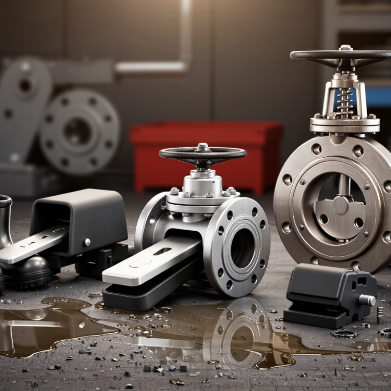
How to Choose a Foot Pedal Valve in 2026?
A foot pedal valve should match the actuator, not just the available space. The 3/2 configuration has three ports and two positions. It suits single-acting cylinders, clamps, and tools that return by spring or external force. Pressing the pedal sends air forward. Releasing it usually exhausts the actuator. Check the return action carefully. A weak spring can create slow or incomplete movement.
The 4/2 configuration controls double-acting cylinders through four ports and two positions. One pedal position extends the cylinder, while the other retracts it. It offers a straightforward circuit with simple directional control. The 5/2 configuration also operates double-acting cylinders, but it provides separate exhaust ports. This arrangement can improve exhaust routing and speed control, especially when silencers or flow regulators are needed. It may also make troubleshooting easier.
I once selected a larger valve, expecting faster motion. The cylinder became harsh instead. That mistake taught me to compare port size, operating pressure, flow demand, and pedal force together. In 2026, consider guarded pedals for busy work areas and detented pedals when the operator needs hands-free positioning. Confirm the valve’s materials and seals against dust, moisture, oil mist, and temperature changes. A specification sheet can look convincing. Real machine testing still matters. Listen for leaking air. Check whether the actuator stops where expected. A small mismatch can cause repeated faults.
When choosing a foot pedal valve in 2026, start with the ISO 1219 symbol, not the catalog photo. The symbol shows the valve’s ports, positions, flow paths, and actuation method. A 3/2 valve suits a single-acting cylinder, while a 5/2 valve commonly controls a double-acting cylinder. Read the symbol first. Confirm whether the pedal returns by spring or stays in position.
Match port size with the air demand. A small port can create pressure loss, slow cylinder movement, and audible exhaust noise. However, a larger port does not automatically improve performance. Compare the valve’s rated flow, often shown as Cv or normalized litres per minute, with the actuator’s required consumption. The U.S. Department of Energy’s Improving Compressed Air System Performance sourcebook reports that compressed air can represent about 10% of industrial electricity use. Poor sizing wastes more than response time.
Check working pressure, minimum actuation pressure, and exhaust capacity separately. A valve rated for 8 bar may not shift reliably at low pilot pressure. In a workshop test, connect a pressure gauge near the actuator, then observe speed under the real load. Static bench results can mislead. I would also allow margin, but not too much; my earlier selections sometimes used oversized valves and gained little. ISO 1219 symbols improve communication, yet they do not replace flow testing, maintenance records, or honest review of the machine’s duty cycle.
Match Port Size, Flow Rate, and Pressure with ISO 1219 Symbols
The chart shows representative flow capacities for common pneumatic foot pedal valve port sizes at approximately 6 bar inlet pressure and a 1 bar pressure drop. Larger ports generally support higher air flow, but the actual capacity depends on the valve design, Cv value, tubing, and fittings. ISO 1219 symbols identify the valve function and connection logic, such as 3/2 or 5/2 directional control, but they do not define flow rate or pressure rating. Always verify the manufacturer’s technical data before selection.
Choosing a foot pedal valve in 2026 requires more than checking port size and operating pressure. The compressed air must match the application. ISO 8573-1 classifies particles, water, and oil in compressed air. Ask for measured results, not vague claims such as “clean air.” Check the air near the valve, because storage tanks and long hoses can change quality.
A workshop inspection should include a particle counter, dew-point reading, and oil measurement when contamination matters. Record the results against the required ISO 8573-1 class. A dusty workshop may need better filtration. Moisture can also cause sticking, corrosion, or unstable motion. Small details matter. Yet test instruments can drift, and one reading may mislead. Repeat testing after maintenance or seasonal changes.
Safety selection must follow ISO 4414 principles. The pedal should not create unexpected actuator movement after pressure returns. Consider guarding, stable mounting, controlled exhaust, and a clearly accessible isolation device. Verify that residual pressure can be released safely before servicing. A valve with the correct pressure rating may still be unsuitable if its pedal is easy to press accidentally. Review the complete circuit, including cylinders, hoses, silencers, and emergency controls. In real installations, space around the pedal is often underestimated. That mistake deserves a second look.
Choosing a foot pedal valve in 2026 requires more than checking port size and operating pressure. Under ISO 13849-1, begin with a documented risk assessment. Identify unexpected actuation, trapped feet, restart hazards, and loss of control energy. The required performance level depends on the machine risk, not the valve alone. A pneumatic valve may control motion, but it may not provide the complete safety function.
Guarding should prevent accidental stepping while allowing intentional operation. Consider a hinged cover, side shields, and enough clearance for safety footwear. The guard should not create a new trip hazard. Test access from realistic positions, including crouching and reaching. Ergonomics matters too. Pedal resistance, travel distance, surface texture, and operator posture affect fatigue and mistakes. A pedal placed too far away may encourage unsafe leaning. Small details matter.
Tips: Map each hazard before choosing the valve. Confirm the safety function and target PLr with a competent engineer. Use monitored valves, redundant channels, or isolation devices only when the risk assessment requires them. Verify stopping time with the actual machine, not a catalogue estimate. Label the pedal clearly, then observe operators during normal shifts. Their workarounds may reveal weaknesses. I would also review the design after installation; assumptions often fail beside dust, oil, and winter gloves. Record validation results, guard tests, fault responses, and maintenance checks. ISO 13849-1 supports structured design, but it does not replace practical testing or informed judgment.
How to Choose a Foot Pedal Valve in 2026?
Cycle life should be your first measurable filter, not a vague durability claim. A 2025 review of industrial supplier datasheets found rated cycles commonly ranging from 500,000 to 5 million operations. However, test conditions differ. Dust, side loading, and rapid switching can reduce real service life. Ask for test-load, temperature, and maintenance details before comparing figures. A valve rated for 2 million cycles may outperform a higher-rated model in dirty workshops.
Material selection affects both feel and survival. Anodized aluminum keeps the pedal light, while stainless steel tolerates moisture and repeated impact better. Reinforced polymers can reduce cost, but their hinges deserve close inspection. For outdoor equipment, IEC 60529 defines IP65 as dust-tight with protection against water jets. IP67 adds temporary immersion protection, typically up to one metre for 30 minutes under controlled testing. That rating does not prove chemical resistance or long-term sealing.
Tips: Match IP protection to the actual cleaning method. Check hinge wear, return-spring force, and port threads during trials. Request 2026 supplier data in writing, including cycle-test conditions and replacement-part availability. I would avoid choosing by IP number alone. It looks precise, but field performance is messier. Also, do not treat a laboratory cycle figure as a guarantee. Human foot pressure varies. So does maintenance.
| Valve configuration | Typical application | Port size | Function | Operating pressure | Typical cycle life* | Body material | Spool / internal material | Seal material | Ingress rating** | Temperature range | Mounting format | 2026 indicative supplier lead time | Best selection priority |
|---|---|---|---|---|---|---|---|---|---|---|---|---|---|
| 3/2-way, spring return | Single-acting cylinders and basic machine controls | G 1/4 or 1/4 NPT | Normally closed or normally open | 0.2–0.8 MPa | 1–3 million cycles | Anodized aluminum or zinc alloy | Nickel-plated brass or stainless steel | NBR; FKM available for higher temperatures | IP54–IP65, depending on guard and enclosure | −5 to 60°C typical | Panel, floor, or foot guard | 2–6 weeks for standard configurations | Low cost and simple return action |
| 5/2-way, spring return | Double-acting cylinders requiring a defined fail position | G 1/4 or 1/4 NPT | Two working ports with exhaust routing | 0.2–0.8 MPa | 1–3 million cycles | Anodized aluminum or zinc alloy | Hard-anodized aluminum or stainless steel | NBR or FKM | IP54–IP65 with protective boot or guard | −5 to 60°C typical | Floor-mounted pedal with safety guard | 3–8 weeks for standard configurations | Repeatable cylinder extension and retraction |
| 5/3-way, closed center | Position-holding circuits and guarded machine operations | G 1/4 or 1/4 NPT | Both cylinder ports blocked at center | 0.2–0.8 MPa | 0.8–2 million cycles | Anodized aluminum or zinc alloy | Stainless steel or treated aluminum | NBR; FKM for elevated temperature service | IP54–IP65 | −5 to 60°C typical | Heavy-duty floor plate | 4–10 weeks for standard configurations | Load holding and controlled stopping |
| 5/3-way, exhaust center | Fast depressurization and pneumatic safety circuits | G 1/4 or 1/4 NPT | Both cylinder ports exhausted at center | 0.2–0.8 MPa | 0.8–2 million cycles | Anodized aluminum or zinc alloy | Stainless steel or treated aluminum | NBR or FKM | IP54–IP65 | −5 to 60°C typical | Floor-mounted with toe guard | 4–10 weeks for standard configurations | Rapid release of stored pneumatic energy |
| Manual pedal valve with lock | Processes requiring a maintained operating state | G 1/4 or 1/4 NPT | Maintained position with mechanical lock | 0.2–0.8 MPa | 0.5–1.5 million cycles | Cast aluminum or zinc alloy | Nickel-plated brass or stainless steel | NBR or FKM | IP54–IP65 | −5 to 60°C typical | Floor plate with heel rest | 3–8 weeks; custom guards may add 2–4 weeks | Maintained output without continuous foot force |
| Safety-covered pedal valve | Industrial machinery with accidental-actuation risk | G 1/4 or 1/4 NPT | Spring return or guarded maintained action | 0.2–0.8 MPa | 1–3 million cycles | Aluminum alloy with steel protective guard | Stainless steel or treated aluminum | NBR; FKM where chemical resistance is needed | IP65; IP67 only when the complete assembly is certified | −5 to 60°C typical | Bolted floor or machine-frame mounting | 4–12 weeks depending on guard design | Protection from unintended activation and washdown |
| Corrosion-resistant pedal valve | Food, packaging, outdoor, or humid production areas | G 1/4 or 1/4 NPT | 3/2-way or 5/2-way manual control | 0.2–0.8 MPa | 0.5–2 million cycles | Stainless steel or coated aluminum | Stainless steel | FKM or approved NBR compound | IP65–IP67 for the complete protected assembly | −10 to 60°C typical | Hygienic or sloped floor mounting | 6–14 weeks; stainless options are often made to order | Resistance to moisture, cleaning agents, and corrosion |
2026 supplier-data reference: Lead times are indicative ranges for standard pneumatic foot-pedal valve configurations commonly offered through industrial distribution and direct manufacturing channels in 2026. Custom materials, special port threads, documentation, safety validation, and low-volume orders can extend the stated ranges.
* Cycle life: The figures are typical engineering ranges rather than universal guarantees. Actual life depends on actuation force, operating frequency, air cleanliness, lubrication, pressure, temperature, contamination, and maintenance. Require a supplier test report for critical-duty applications.
** IP rating: IP ratings apply to the tested complete enclosure or pedal assembly under IEC 60529. A bare pneumatic valve should not be assumed to have the same IP rating as a guarded or sealed foot-control assembly.