
X

Partner Login

Enter your username and password here on order to log in on the partner portal:

No registered partner yet?

Register now

How to Choose the Right Thread Milling Insert?

Choosing the right Thread Milling Insert is not a simple catalog exercise. The correct choice depends on thread size, material, machine stability, coolant delivery, and production targets. A carbide insert that performs well in aluminum may fail quickly in hardened steel. Small details matter.

Dr. Tony Schmitz, a respected machining dynamics researcher, offers a useful principle: “Machining decisions should be validated by measured results, not intuition alone.” That idea applies directly to thread milling. Operators should inspect the first thread, check flank quality, measure pitch diameter, and monitor cutting load. A clean edge is encouraging. It is not proof of complete success.

This guide examines insert geometry, grade, coating, and cutting parameters. It also considers chip evacuation and toolpath strategy. Those factors often decide whether the thread is accurate or merely acceptable. In real workshops, vibration, worn holders, and inconsistent workholding can change the result. Ignoring them is a common mistake.

There is no universal insert.

A reliable selection begins with the workpiece and the required thread standard. Match the insert profile carefully. Confirm the insert’s pitch range and diameter capability. Then compare the manufacturer’s recommended speeds and feeds with actual machine behavior. Published data provides a starting point, not a guarantee.

Some recommendations may need adjustment. That is normal. Careful testing, documented measurements, and honest review of failed attempts lead to better decisions. The goal is not only faster production. It is stable, repeatable, and verifiable thread quality.
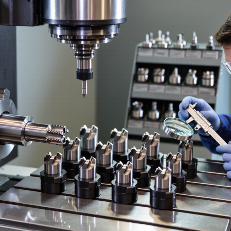
How to Choose the Right Thread Milling Insert?

Understanding Thread Milling Inserts and Their Cutting Role

How to Choose the Right Thread Milling Insert?

A thread milling insert is not simply a replaceable cutting edge. It controls how material becomes a precise internal or external thread. During milling, each tooth removes a small chip at a controlled position. This spreads cutting pressure across the tool and reduces sudden loading. In practice, I watch the chip shape before changing cutting speed. Powdery chips may suggest rubbing, while long, hot chips can indicate poor evacuation. The result is not always perfect. Machine rigidity, tool overhang, and coolant delivery can change the cutting role completely.

Match the insert to the thread pitch, diameter, and workpiece material. A fine pitch usually needs careful feed control and a sharp cutting edge. A coarse pitch can create heavier radial loads. Full-profile inserts form the complete thread crest, while partial-profile inserts offer more flexibility across different diameters. For hardened steel, a strong edge and stable geometry are important. Softer alloys may require a sharper edge to prevent built-up material. These choices sound simple, but the wrong geometry can leave torn flanks or uneven crests.

Check the holder, insert seat, and clamping condition before cutting. Even a suitable insert performs poorly with vibration. I prefer a short tool extension and steady coolant flow. Start with conservative parameters, then inspect the first thread using magnification and a calibrated gauge. Listen closely. A harsh, irregular sound often appears before visible damage. Choosing only by catalog data is tempting, yet real machines rarely behave identically. Record the result, question the first assumption, and adjust one variable at a time.

Matching Insert Geometry to Thread Size, Form, and Material

How to Choose the Right Thread Milling Insert?

Choosing a thread milling insert starts with the thread form, not the toolholder. Match the insert profile to the required thread standard, pitch, and diameter. A full-profile insert controls the crest and root accurately, while a partial-profile insert can cover several thread sizes. However, it may leave the crest unfinished. Check the drawing carefully. A small mismatch can create poor engagement or assembly problems.

Material changes the geometry decision. For stainless steel, a sharper cutting edge and positive rake can reduce built-up material around the insert. For hardened steel, stronger edge support and a smaller cutting depth may improve stability. Aluminum often needs generous chip space and polished cutting surfaces. I have seen operators blame the insert when the real issue was excessive radial engagement. That mistake is easy to repeat.

Tips: Confirm the thread pitch before ordering. Measure the insert’s included angle with a tool microscope when accuracy matters. Use coolant suited to the workpiece, and clear chips from deep holes. Begin with conservative cutting data, then adjust after checking flank finish and tool wear. Do not ignore tool deflection. It can make a correct insert produce an incorrect thread.

Selecting the Right Grade, Coating, and Cutting Edge

Choosing a thread milling insert starts with the workpiece, not the tool catalog. In daily machining, I match the insert grade to hardness, toughness, and cutting temperature. A tougher carbide grade handles interrupted cuts and unstable setups better. A harder grade usually resists wear during long runs in abrasive materials. For aluminum, a sharp, polished edge helps prevent built-up material. For stainless steel, a tougher edge and controlled heat are often safer choices.

Coating selection should support the cutting conditions. A wear-resistant coating suits dry or high-temperature machining, while a smoother coating can reduce friction and chip adhesion. Coating alone cannot fix poor coolant delivery or excessive speed. I check the recommended cutting range, then make a small test cut. Small details matter. A thread with torn flanks may indicate heat, vibration, or an unsuitable grade rather than a damaged insert.

The cutting edge deserves equal attention. A positive rake edge lowers cutting pressure and protects thin walls. A stronger edge is preferable when the setup lacks rigidity. Corner radius also affects thread quality, especially near shoulders or interrupted surfaces. I once selected an overly sharp insert for a flexible fixture; the first threads looked clean, but vibration appeared deeper in the hole. The better choice was a slightly stronger edge with a slower feed. That result reminded me that textbook recommendations need practical verification. 马会

How to Choose the Right Thread Milling Insert? — Selecting the Right Grade, Coating, and Cutting Edge

Workpiece or Requirement Carbide Grade Characteristics Coating and Surface Cutting-Edge Choice Practical Selection Notes
Low-carbon and general-purpose steels A balanced carbide grade with suitable wear resistance and toughness is a practical starting point. A wear- and heat-resistant coating, such as TiAlN or AlTiN, is commonly used for steel machining. A lightly honed edge can help resist chipping; avoid an unnecessarily heavy hone that increases cutting forces. Match the insert to the steel’s hardness and the machine’s rigidity. Use stable clamping and follow the insert maker’s cutting data.
Stainless steels A tough grade is often preferred because stainless steels can work-harden and generate substantial cutting heat. A heat-resistant coating may be suitable. For some applications, a sharp, polished, uncoated or specialized surface can help limit built-up edge. A sharp, positive edge generally reduces cutting forces; use enough edge strength to prevent chipping. Maintain a consistent feed and avoid rubbing or dwelling, which can promote work hardening. Use coolant when appropriate for the operation and machine.
Cast iron A wear-resistant grade is often appropriate for the abrasive nature of many cast irons; tougher grades may be needed for interrupted cuts. Wear-resistant coatings are commonly considered. Select the coating and grade together for the specific cast-iron type and cutting conditions. A stronger, lightly honed edge can improve resistance to edge damage, especially where the cut is interrupted. Account for the casting’s abrasiveness and inclusions. Dry machining may be suitable in some setups, but follow tool and process recommendations.
Aluminum and other non-ferrous alloys A sharp, fine-grain carbide grade is often selected to support a keen edge and good surface finish. A polished, uncoated surface or a coating intended for non-ferrous materials, such as TiB2, may help reduce material adhesion. Choose a sharp, positive edge with a polished rake face where available. Avoid coatings or edge preparations that are not intended for the alloy, as they may increase adhesion or cutting forces. Confirm suitability for silicon-rich aluminum.
Titanium and heat-resistant alloys A tough, heat-resistant carbide grade is generally preferred; these materials can retain heat at the cutting edge. Consider a coating designed for high-temperature cutting, selected in accordance with the insert supplier’s guidance for the specific alloy. A sharp but sufficiently supported edge can help balance cutting forces and edge strength. Use rigid workholding and avoid excessive tool engagement. Apply conservative starting conditions and monitor wear closely.
Hardened steel or high-hardness components Select a grade explicitly rated for the workpiece hardness and operation; conventional carbide grades may not be suitable at very high hardness. Use only a coating and insert grade approved for the specified hardness and cutting method. A stronger edge may resist chipping, but the correct edge depends on hardness, engagement, and machine rigidity. Check the insert’s stated hardness range before cutting. For very hard materials, a different cutting-tool material or process may be required.
Unstable setup, long overhang, or interrupted engagement Favor toughness and resistance to edge chipping over maximum wear resistance alone. Choose a coating compatible with the material and temperature; coating selection cannot compensate for poor rigidity. Use a more robust edge preparation if recommended for the insert, while avoiding excessive edge rounding. Improve workholding and minimize overhang where possible. Reduce cutting load if vibration or edge damage occurs.
Fine thread finish or small thread features A grade that maintains a stable, sharp cutting edge can support consistent thread form. A smooth, low-adhesion surface may help where built-up material affects the finish. A sharp, accurately formed edge is important; confirm the insert profile matches the required thread standard and pitch. Check thread profile, pitch, insert hand, and toolpath. Inspect the first thread with an appropriate gauge before continuing production.

Selection reminder: Grade, coating, and edge preparation should be chosen as a combination. Verify compatibility with the workpiece material, hardness, thread profile, machine rigidity, coolant strategy, and the insert manufacturer’s current cutting recommendations.

Checking Machine Compatibility and Milling Conditions

How to Choose the Right Thread Milling Insert?

Checking Machine Compatibility and Milling Conditions

Machine compatibility should come before insert selection. Check the spindle taper, holder size, machine power, and controller capacity. The tool must fit the machine’s maximum rpm and interpolation limits. A rigid setup matters greatly when cutting hardened or deep-threaded materials. The machine may run, but not well.

USCTI and AMT industry reports recorded more than 2 billion dollars in annual U.S. cutting-tool consumption in recent years. This scale reflects how strongly productivity depends on correct tooling decisions. For thread milling, confirm the insert’s pitch range, thread profile, cutting diameter, and material grade. Then set cutting speed, feed per tooth, axial depth, and radial engagement. ISO 8688 tool-life testing guidance also shows why controlled cutting conditions are important. Excessive speed can create flank wear. Low feed can rub the edge. I still see this mistake in otherwise capable workshops.

Tips: Begin with the insert supplier’s recommended speed and feed range. Reduce speed by 10 to 15 percent when machine rigidity is uncertain. Use coolant or directed air according to the workpiece material and chip pattern. Watch the first thread under magnification. A bright, torn flank is a warning. Measure pitch diameter after a short trial, not after a full batch. Published formulas help, but real machine behavior may disagree. That is where careful adjustment becomes practical expertise.

How to Choose the Right Thread Milling Insert?

Relative decision weight for selecting a thread milling insert. The scores reflect common machining practice and are not linked to any specific manufacturer or brand.

Key point: Confirm spindle speed, feed control, toolholder capacity, thread profile, workpiece material, cutting speed, chip evacuation, and coolant access before selecting the insert.

Evaluating Tool Life, Thread Quality, and Overall Cost

How to Choose the Right Thread Milling Insert?

Choosing a thread milling insert starts with the workpiece, not the catalog. Material hardness, thread diameter, pitch, and machine rigidity all affect insert performance. In shop trials, I watch flank wear after a fixed number of holes. A sharp edge can produce clean flanks, while a worn edge leaves torn material near the thread crest. Measure the wear. Do not rely only on sound or cutting color.

Thread quality depends on more than insert geometry. Check the thread with a calibrated gauge, then inspect the crest under magnification. Burrs, uneven flanks, and a rough root may indicate incorrect cutting data or poor chip evacuation. Coolant direction matters, especially in deep holes. A stable insert should maintain pitch accuracy across repeated cycles, not just produce one acceptable thread.

Tool life must be judged against total cost. Include insert price, indexing time, machine time, rejected parts, and inspection effort. A cheaper insert may become expensive when it requires frequent replacement. I once chose a lower-cost option and ignored the extra cycle time. The result was disappointing. Still, the mistake revealed an important limit: maximum tool life is not always the best target. Consistent thread quality often matters more than a few additional holes. Record results by material and thread size, because one insert can perform well in aluminum and poorly in hardened steel.