


 Distributors
  SDS Download
  Contact
 Partner Login
Enter your username and password here on order to log in on the partner portal:
No registered partner yet?
Register nowWhy Choose a Tapered Motor Shaft for Better Performance?
Choosing a Tapered Motor Shaft can improve power transmission, alignment, and service reliability in demanding machinery. Its conical profile creates a firm connection between the motor shaft and the mounted component. This design reduces unwanted movement during startup, braking, and repeated load changes. Less movement matters.
In practical installations, technicians often notice smoother operation after replacing a loose straight-shaft connection. A tapered fit can distribute contact pressure more evenly when manufactured and installed correctly. It also simplifies component removal, especially when a suitable extraction feature is included. However, performance depends on more than the shaft shape. Accurate taper angles, controlled surface finish, correct keyway dimensions, and proper tightening torque remain essential. Small errors can create vibration, fretting, or premature bearing stress.
Engineering guidance should come from motor manufacturers, qualified designers, and documented industry standards. Load type, rotational speed, temperature, and maintenance access deserve careful evaluation before selection. A shaft that performs well in a conveyor may fail prematurely in a high-cycle pump. That limitation is easy to overlook. Material choice also affects fatigue life, corrosion resistance, and machining stability. Inspection records can confirm whether the taper remains within specified tolerances after repeated service.
The best decision balances performance, cost, installation effort, and long-term reliability. A tapered design is not automatically superior. It becomes valuable when its geometry matches the application, coupling, and maintenance plan. Careful measurement still matters more than confident assumptions.
What Is a Tapered Motor Shaft?
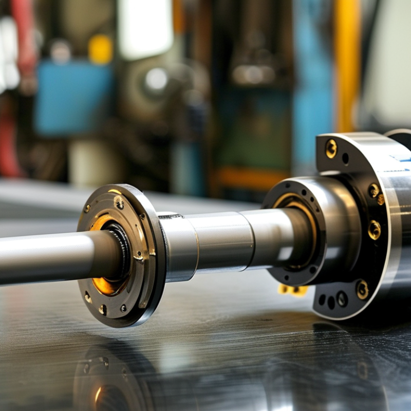
A tapered motor shaft is a rotating shaft with a gradually changing diameter. One end is wider, while the other end is narrower. This conical shape fits into a matching tapered hub, coupling, or pulley. It is not merely a thinner shaft. The taper creates a tight mechanical connection as the parts seat together.
In practical maintenance work, this design can improve torque transfer and reduce movement between the shaft and mounted component. A properly fitted taper also supports accurate alignment, which can help limit vibration and uneven bearing loads. Some shafts include a keyway, but the taper should still provide most of the centering effect. Small errors matter. Dirt, burrs, or oil on the mating surfaces can prevent full contact and create runout.
The taper angle, shaft dimensions, surface finish, and hub material all affect performance. Engineers normally confirm these details before selecting a replacement. Guessing from appearance is risky. A shaft that looks compatible may have a different taper standard or seating length. I have seen installation problems caused by tightening alone, without checking contact marks. That approach can hide poor fit and damage the hub. Tapered shafts are not automatically better for every motor; they work best when the load, speed, mounting method, and maintenance conditions match the design.
Why Choose a Tapered Motor Shaft for Better Performance? - What Is a Tapered Motor Shaft?
| Performance Dimension | Tapered Motor Shaft | Straight Motor Shaft |
|---|---|---|
| Definition | Conical interface A shaft whose diameter changes gradually along the engagement length. The mating hub, rotor, pulley, or coupling has a matching internal taper. | Constant diameter A shaft with a uniform cylindrical diameter, normally secured with a key, clamp, set screw, spline, interference fit, or another retaining method. |
| Typical Taper Geometry | Common taper ratios are approximately 1:10 to 1:20, meaning the diameter changes by one unit over a 10- to 20-unit axial length. The exact taper must match the mating component. | No conical taper is present. The shaft diameter remains nominally constant over the mounting area. |
| Torque Transmission | Torque can be transmitted through friction created by the wedging action, often supplemented by a key, tang, or locking feature when required by the design. | Torque is commonly transmitted through a keyway, spline, clamping force, friction fit, or set-screw connection. The selected method determines the allowable torque. |
| Self-Centering Capability | The matching tapered surfaces help center the mounted component during assembly, provided that the taper, surface condition, and contact pattern are correct. | Centering depends mainly on dimensional clearance, the hub bore, bearing arrangement, pilot diameter, or an additional locating feature. |
| Runout Control | Can provide low repeatable runout when the mating surfaces are accurately machined, clean, and fully seated. Contamination or incorrect seating can increase runout. | Runout is influenced by bore-to-shaft clearance, key fit, hub alignment, machining accuracy, and the quality of the retaining method. |
| Assembly and Removal | The component is installed by axial seating and is often removed with a drawbolt, threaded extraction hole, or dedicated release mechanism. Correct extraction provisions are important. | Assembly is generally straightforward, but removal may require a puller if the fit is tight. Set screws and keys can complicate disassembly when damaged or corroded. |
| Axial Retention | The taper can generate strong axial seating, but a separate nut, bolt, washer, retaining ring, or drawbar is normally required to maintain the connection under operating loads. | Axial retention is usually provided by a shaft shoulder, nut, collar, retaining ring, clamp, end plate, or another dedicated feature. |
| Load Distribution | A properly fitted taper distributes contact pressure over a larger conical surface rather than concentrating the load at a single set screw location. | Load distribution depends on the fit and fastening method. Keyways and set screws may create local stress concentrations if not properly designed. |
| Stress and Fatigue Considerations | A smooth taper can avoid some abrupt diameter changes, but the small end, keyway, threads, shoulders, and surface defects still require fatigue analysis. | Stress concentration may occur at keyways, snap-ring grooves, shoulders, and abrupt diameter transitions. Fillet radii and shaft sizing are important. |
| Maintenance Requirements | Keep the mating surfaces clean, inspect for fretting or galling, verify seating, and apply lubrication only when specified by the design. Excess lubricant can reduce frictional holding. | Inspect keys, set screws, clamps, fits, and retaining hardware. Check for looseness, fretting, corrosion, and wear at the connection. |
| Best-Suited Applications | Frequently selected for removable rotors, precision couplings, tool interfaces, pulleys, fan assemblies, and applications requiring repeatable positioning. | Commonly used for general-purpose motors, simple pulleys, gears, sprockets, couplings, and applications where a cylindrical connection is adequate. |
| Main Design Limitation | The shaft and mating component must use the same taper specification. Poor contact, incorrect dimensions, over-tightening, or contamination can cause poor seating and damage. | The connection may need additional components for accurate centering and high torque. Keyways, clamps, or set screws must be sized for the expected mechanical loads. |
| Selection Checklist | Confirm taper ratio, large and small diameters, engagement length, material strength, surface finish, axial retention, permissible runout, balance requirements, and removal method. | Confirm shaft diameter, fit class, key or spline dimensions, hub length, retaining method, allowable stress, permissible runout, and service environment. |
Engineering note: A tapered motor shaft does not automatically provide higher torque capacity or better performance. Its advantages depend on accurate matching parts, adequate contact area, proper retention, correct installation, and verification of torque, speed, fatigue, and safety requirements.
